Ask a question
In the production process, such a part will be encountered. As shown in Fig. 1, the part has a small outer shape and five φ25H9 holes are evenly distributed on the arc, and the center of each hole intersects with the center of the arc at the same point. How to easily and conveniently machine these inclined holes and ensure accuracy becomes a tricky problem.

figure 1
2. Analyze the problem
According to the traditional process scheme, there are three processing methods: 1 scribe line method, draw the position of each hole, and machine the hole according to the line. However, due to the large radius of the arc, the scribing is difficult and the accuracy is difficult to ensure. 2 Place the part so that the center of the arc coincides with the center of rotation of the table, and rotate the hole of the table. However, this method requires the use of a large-scale machine tool (that is, the radius of rotation of the table must be larger than the radius of the arc), and the two centers must be completely coincident, which is extremely difficult to operate. 3 Using five-axis CNC machine tools, this method is simple and easy to operate. However, due to the limitation of the machine tool, if there is no five-axis machine tool, it cannot be processed and the processing cost is high. How to machine such parts on conventional machine tools has become an urgent problem to be solved.
The parts are placed at any position on the workbench. We require the straight side of the part to be perpendicular to the machine tool spindle, then clamped, and the parts rotate with the table. Therefore, the hole to be machined after rotation will not be directly under the spindle, the center of the hole and the center of the spindle. A distance will be generated in the X-axis direction, and the table can be processed by compensating the distance in the X-axis direction, so it is difficult to determine the compensation distance.
3. Solve the problem
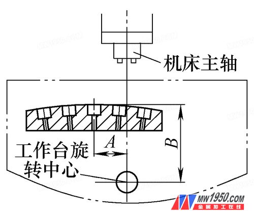
(1) Drawing method to determine the compensation distance Use AutoCAD software to simulate the position of the table and the rotating center on the computer, and then measure the A and B values ​​according to the clamping position (the straight edge of the part is perpendicular to the machine tool spindle when clamping) , draw the exact position of the part on the workbench, as shown in Figure 2, the worktable compensates the distance A, you can machine the middle hole.

figure 2
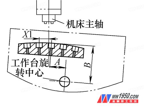
The table rotates clockwise by 4° according to the pattern. As shown in Fig. 3, the X1 value is measured. In the actual machining, the table compensates the distance X1 along the X-axis direction, and the 4° position hole can be processed.

image 3
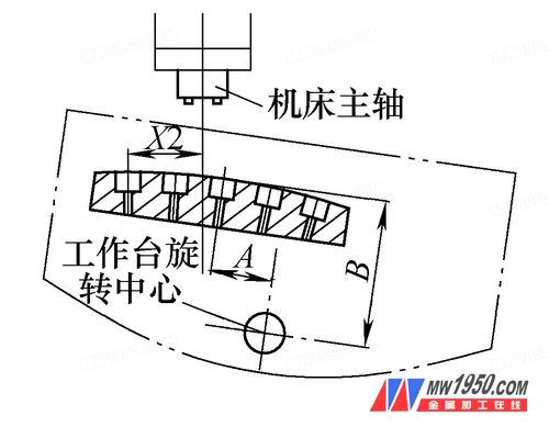
The table rotates 8° clockwise. As shown in Fig. 4, the X2 value is measured. In the actual machining, the table compensates the distance X2 along the X-axis direction, and the 8° position hole can be processed.

Figure 4
The position of the 4° and 8° holes in the counterclockwise direction is X in the same way, and it can be processed.
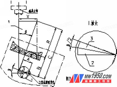
(2) Calculation method to determine the compensation distance Taking the concave arc as an example, the table rotates the β angle clockwise, as shown in Fig. 5, the right triangle 3 and the right triangle 2 are congruent, and the triangle 3 is known to have a straight edge A. The angle is β/2, the other right angle is obtained by Atan(β/2); in the right triangle 1, the angle β is known, and the oblique side is the sum of the three sides of the R, B and the triangle 3 You can solve for X.

Figure 5
The formula for calculating the compensation distance of the table along the X-axis direction after the table rotates clockwise β is
X=[C+Atan(β/2)]sinβ, where C=R+B
The formula for calculating the compensation distance of the table along the X-axis direction after the table rotates counterclockwise β is
X=[C-Atan(β/2)]sinβ, where C=R+B
The method of calculating the convex arc and the concave arc is the same, and will not be described here. Only the calculation formula is given.
The formula for calculating the compensation distance of the table along the X-axis direction after the table rotates clockwise β is
X=[C+Atan(β/2)]sinβ, where C=R-B
The formula for calculating the compensation distance of the table along the X-axis direction after the table rotates counterclockwise β is
X=[C-Atan(β/2)]sinβ, where C=R-B
4. Conclusion
Since the A and B values ​​are the basic data for drawing or calculation, the value must be accurately measured. It can be measured by installing a checker bar in the positioning hole of the rotation center of the table. In order to accurately measure the A and B values, the shape of the part is finished by fine milling. The parallel and vertical control of each surface is within 0.02mm, and the surface roughness value of the R and R surfaces is Ra≤1.6mm.
Using the method described above, this part was successfully processed on our TH6350 horizontal machining center (workbench 500mm×500mm). After testing, the accuracy meets the design requirements, which proves that this method is economical, simple and reliable, and worthy of promotion.
Paint Brush,Paint Brush Clip Art,Paint Brush Drawing,Paint Brush Cleaner
Paint Brush, Roller Brush Co., Ltd. , http://www.nbpaintbrush.com