CNC programming technology has entered the stage of automatic graphics-based programming and is getting more and more widely used. In the research, the author chooses AutoCAD drawing software as the graphic input platform, combines the AutoCAD software with the numerical control platform, and directly reads the graphic data of the DXF graphic exchange file by programming the interface program to realize the automatic generation of the numerical control code of the two-dimensional graphics. Furthermore, the automatic text editing technology based on AutoCAD is further studied. The text is changed into AutoCAD graphic object, which is transformed into DXF file containing path information and AutoCAD-based shape file to realize automatic extraction of Chinese character strokes, and the method of automatic text programming is summarized.
The NC code automatically generated by graphics and text finally controls the servo drive through the motion control card to realize machining on the CNC platform.
1. Processing of graphic information and automatic programming of numerical control programs
(1) Extraction of graphic information of DXF file The complete DXF file consists of 6 segments and end markers. These 6 segments are the file header, class segment, table segment, block segment, entity segment and object segment, respectively storing the version number and System variables, system-defined various class information, system table information, graphic block information, and all non-geometric entity information in the table segment, block segment, and entity segment.
After the part drawing is saved as a DXF file, the graphic entity information needs to be read from the DXF file. The graphic information drawn by AutoCAD is included in the 6 segments of the DXF file. The geometric information related to the geometry is included in the solid segment. If there are graphic blocks in the graphic, after the breakup, the entities contained in the block will still appear. In the entity segment.
For automatic programming, only the physical geometry information needs to be concerned, so only the physical segment of the DXF file needs to be read and processed. The process of information extraction is as follows: open the DXF file, read the file line by line, loop through, read the content of the line as "ENTITIES", start the physical segment of the table name, and then continue reading. When the content of the line is "LINE", it is a straight line; if it is "CIRCLE", it is a circle; if it is "ARC", it is an arc; then the corresponding entity data is read. When the content of the line is "ENDSEC", it indicates that the end of the segment has reached the end of the segment, and the entity extraction process ends.
(2) Processing of graphic information Considering the process requirements of actual processing, the extracted DXF file graphic information cannot be directly used for numerical control programming. The processing of DXF graphic information includes data storage structure design, arc endpoint coordinate calculation, arc feature discrimination, sorting processing, etc., so that the final data can be used for NC program writing. The NC code file is automatically generated based on the processed graphic data information.
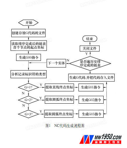
(3) Generate NC code file After all the entity information is obtained, and the sorting is completed, the code conversion can be started.
The system generates NC code according to ISO standards. Traverse the nodes in the part object list and find the pointer of the part object to be processed. In the process of generating the part machining program, firstly, the starting point of the first geometric element in the linked list is extracted as the starting point coordinate of the part processing track, and the G00 (space-free positioning) command is added. Then, the data information in the linked list is read one by one, and the type of each graphic element is determined by comparing the numerical values ​​of the recorded identification numbers G, the parameter information of the primitive object is read, and the coordinate values ​​or coordinates of each processing segment are calculated. Quantity, according to the CNC instruction code specification to write the NC program. Transition code instructions are added between two different graphic outlines for uninterrupted machining. Using absolute coordinate programming, the program flow chart is shown in Figure 1.
2. Automatic text programming based on AutoCAD
(1) Converting text into a DXF file containing path information Since in AutoCAD, text is treated as a Mtext (multi-text) object, it is a whole, and in order to implement text processing, it is necessary to change the text into a graphic object. Using AutoCAD to generate text, and through AutoCAD to achieve the conversion of text objects to graphic objects, to generate CNC machining code, mainly using AutoCAD Txtexp command.
(2) AutoCAD vector Chinese character automatic programming The special vector font library (extension .shx) in AutoCAD is obtained by compiling the shape file (.shp). Using the decompiler software SHX2SHP, you can get ASCII files in .shp format.
The shape file converted from the vector font library font file is a Chinese character defined by a shape file. The large font file gbcbig.shx in the AutoCAD vector font library is decompiled into gbcbig.shp file, and the gbcbig.shp file is taken as the research object to realize the extraction of Chinese character stroke data and the automatic programming of the NC program. The Chinese character stroke data information is extracted from the shape file, and all the Chinese character stroke data information is obtained, and after the coordinate conversion is completed, the code conversion can be performed, and the system generates the G code according to the ISO standard.
3. Computer simulation of CNC machining process
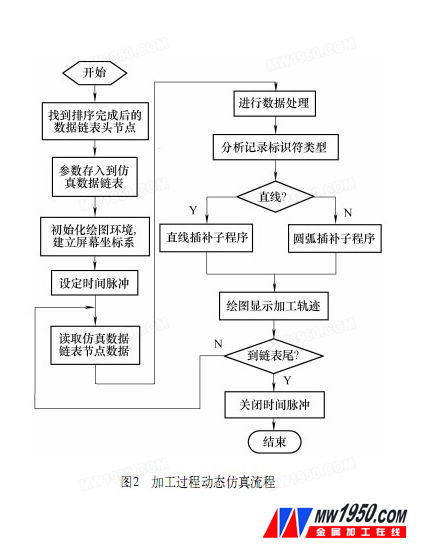
Perform static and dynamic simulation of the location file. The process of static simulation uses the head node of the head element of the sorted linked list as the starting point, and the processing track is redrawn in the form of drawing in the window of Visual C++6.0. Dynamic simulation is the machining simulation. The simulation process initializes the simulation interface, sets the position of the graphic display, inputs the starting point of the simulation processing, and uses the head node of the head element of the sorted linked list as the starting point in the system, and then reads it line by line. Take the graphic information contained in the code, and use the digital integral interpolation algorithm and the system timer to perform the simulation display of the processing process on the screen according to the order of the linked list records. The process is shown in Figure 2.
4. System design and implementation
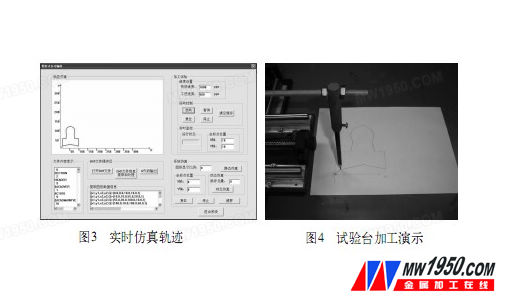
VC++6.0 is used as the development tool, and the numerical integration method is used as the basic principle. The whole system is divided into graphic information reading module, graphic information processing module, NC code generation module, system simulation module, text automatic programming module and processing test module. The system example is shown in Figure 3 and Figure 4.
5 Conclusion
Based on the detailed analysis of DXF file structure and the research of AutoCAD shape file, using the modular idea and C++ language object-oriented programming technology, a simple and intuitive, user-friendly automatic programming system is realized. After debugging, it can extract the geometric information of parts and text strokes obtained by AutoCAD drawing.
CNC Engraving Diamond Drills with high accuracy, high quality, high service life by the superabrasive, Dicing Saw technology, automatic production lines and precision equipment, and our products have obtained the trust of numerous customers with its stable quality. Sail not only making specific products according to customer drawings and samples, but also providing grinder design.
product properties
Higher working precision
Higher working quality
Higher working life
Grit size to 7000 mesh
manufacturing objects
Our drills are mainly used in cell phone chips, window glass lenses, digital products, jade, carbide and so on.
Product classification
hole drill edge drill
Composite drill coordinate drill
Grit size
CNC Engraving Diamond Drills
CNC Engraving Diamond Drills,CNC Engraving Diamond Hole Drills,Sail Coordinate Drills
Suzhou Sail Science & Technology Co., Ltd. , http://www.sail-abrasives.com