The production of powertrains is often composed of a large number of metal cutting machine tools, such as engine blocks, cylinder heads, gearbox housings, etc. Most of these parts are processed by wet machining, which requires the use of cutting fluid for cooling. Cutting fluid and cutting chips are one of the main pollution sources in the machining workshop. Reducing the amount of cutting fluid and properly handling it is not only the current demand for clean production, but also an inevitable choice for energy saving, emission reduction and cost reduction.
Automobile production is a typical representative of mass production mode. The power assembly workshop has dense processing centers and fast tempo. It requires efficient cooling and filtration processing system, and the blank material is relatively simple (mostly cast aluminum and cast iron), which is uniform for cutting fluid. Centralized processing offers the possibility. The centralized cooling and filtration system is highly efficient, energy-saving and environmentally friendly. It is being adopted more and more widely by domestic and foreign car companies. It is extremely urgent to use it properly to achieve its maximum efficiency. This paper takes the cutting fluid used in the machining center as an example, focusing on the treatment of cutting fluid.
Cutting fluid and treatment
1. The role of cutting fluid
The cutting fluid is divided into two types: cutting oil and water-soluble cutting fluid. The water-soluble cutting fluid is divided into three types: fully synthetic, semi-synthetic and emulsified. The processing center generally uses an emulsified water-soluble cutting fluid. The cutting fluid in metal processing mainly plays the role of cooling, lubricating chip removal, rust prevention and cleaning. Due to metal deformation and friction during metal cutting, a large amount of heat is generated. If the heat is not taken away in time, heat will accumulate on the tool, affecting Tool cutting performance. At the same time, a large amount of chips are generated during cutting. If the chips are not removed from the cutting area in time, the surface will be scratched and even the tool will be bonded. Therefore, it is necessary to clean the chips. There is a large amount of water vapor around the iron parts. Under the action of local high temperature, the workpiece is extremely rusty, and the cutting fluid also plays a role of rust prevention.
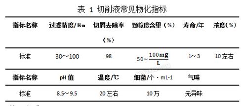
2. Cutting fluid filtration physical and chemical indicators
Since the cutting fluid is related to the processing quality and stability, and the tool life, the purified cutting fluid needs to be monitored in real time, and can be used after it meets the requirements. There are many monitoring items for the filtered liquid, mainly including concentration, pH value, filtration precision, etc. The specific parameters are shown in Table 1.
3. Processing method
The cutting fluid filtration forms are divided into four categories: precipitation filtration, crevice filtration, centrifugal filtration and magnetic filtration. The machining center generally uses two methods: gap filtration and centrifugal filtration. The principle is shown in Figure 1. There are many kinds of media used for crevice filtration. Common filter media include filter screen, filter paper, filter core, filter cartridge, filter bag and fiber powder.
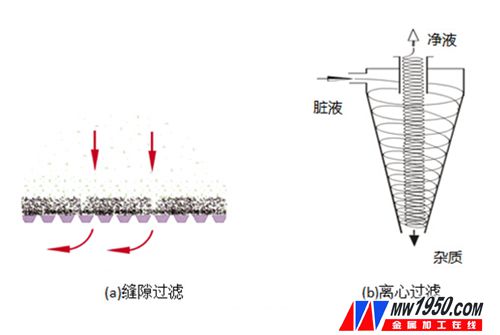
Figure 1 Principle of filtration The choice of filter media is very important. The selection of filter media needs to be determined according to the filtration accuracy and flow rate. Since it is directly related to the later use effect, it is necessary to select it according to the actual situation. Different types of machine tools produce different chip shapes. For example, the machining center generally produces larger particle chips. Gravity filtration can be used for primary filtration. The grinding machine produces fine powder. Small particles can pass through the filter medium, which is easy to produce sludge. As shown in Figure 2, consider using a magnetic filter or filter cartridge to increase the recoil function. The cylinder block and cylinder head are generally cast aluminum or cast iron material. Generally, the large particle chips are settled to the bottom of the tank by sedimentation method, and then lifted out of the liquid surface by the scraping board, and then the filter paper is used to filter small particle impurities.

Figure 2 Metal sludge
Cooling filter system
As mentioned above, the dirty liquid contains a large amount of impurities, and it is necessary to select a reasonable and cost-effective filtration scheme. According to the size of the cooling filter system and the number of machine tools supplied, it can be divided into two types: single type and centralized type.
1. Single cooling filter system
The machining center is generally equipped with a single scraper chain and a cooling filter unit. As shown in Figure 3, the dirty liquid is filtered and cooled, and recycled. The large particle chips are sent to the chip scraper through the scraping chain. After the dirty liquid is collected, the gravity of the liquid is filtered through the filter paper. The system has the advantages of low cost, flexible layout, strong independence, etc., but the disadvantages are also obvious, such as the life of the cutting fluid. Short, polluted environment, large maintenance workload, etc.

Figure 3 Single cooling filter system For large enclosed constant temperature plants, the cleanliness and temperature control requirements are high, while the single-machine coolant tank is an open structure, and the heat is directly distributed in the workshop, which makes the workshop hot and has a great influence on the working environment. At the same time, due to the layout, the tank volume is often only a few cubic meters, the defoaming and heat dissipation are poor, and the cutting fluid is prone to foam overflow and leakage. In actual use, due to the need to control the detection one by one, it brings many negative effects, such as frequent liquid addition and liquid change, resulting in slippery around the cooling box, which has potential safety hazards. Each machining center is equipped with a filter cooling device that is too distracting to handle the chips in depth, especially for large plants, where cutting fluid maintenance and waste disposal are enormous. It is the above shortcomings that limit the range of use of single-machine cooling filtration.
2. Centralized cooling filtration system
The single-machine cooling filtration system cannot meet the requirements of large-scale factories. The centralized cooling filtration system with high degree of automation, energy saving and environmental protection is more and more widely used, especially for engine and transmission factories.
(1) System composition The centralized cooling filtration system consists of a filtration system, a liquid supply and return system, an aeration system, a degreasing system, and a pipeline flushing system.
There are many kinds of filtration system solutions, each with its own merits, but the basic ideas are the same. The general idea is that the large particle chips rely on gravity sedimentation separation, and the pressure difference is generated on both sides of the filter unit by the pump group or gravity, the cutting fluid passes, and the impurities cannot pass, thereby obtaining the clean liquid. Different filter units, different occasions and effects, there are various combinations, as shown in Table 2.

At present, our company's new factory cylinder and cylinder head line adopts a star filter unit: the metal filter is filled with milky fiber, commonly known as pre-coated powder (pre-coated powder is stirred by fiber powder and liquid), by special equipment. The filter unit is injected, as shown in Fig. 4, the liquid is filtered through the gap between the pre-coated powders, which is a type of slit type filtration. After the service life of the pre-coating powder is over, the filtration pressure is increased. After the control system detects that the negative pressure of the outlet pipe is increased, the filter unit can be lifted by the mechanical device, and the failed block-shaped pre-coated powder is removed from the filter screen by vibration. Peeling, discharging the system through the scraping chain, the filter unit resumes operation when the pre-coating powder is refilled. The structure eliminates the hidden trouble of filter failure after the filter paper structure is broken, and has high filtration precision, up to 30 μm, and eliminates the highly polluting waste filter paper, thereby reducing the cost pressure.

Figure 4 star filter unit structure
The liquid supply and return system consists of a liquid tank (precipitation tank, dirty liquid tank, clean liquid tank), a liquid return pump, and a heat exchanger. The tank is arranged in two types, above and below ground. The above-ground tanks and pipelines are all located on the ground, while the underground tanks place the return tanks and tanks under the ground. This scheme is very good. Use the underground space of the factory.
The liquid supply pump can be used with a variable frequency pump or a constant frequency pump. Since the liquid volume of the machine tool is not fixed and there is fluctuation, and the machine tool has a constant requirement for the supply pressure, the variable frequency pump is preferred, which has the advantages of energy saving, low noise and the like. According to the installation position of the pump, it is divided into two types: positive pressure filtration and negative pressure filtration. The negative pressure filtration combines the filter pump and the liquid supply pump into one, which is simple in structure and energy-saving.
The heat exchanger is the first layer guarantee to ensure the temperature of the cutting fluid. In order to ensure the proper performance and processing accuracy of the cutting fluid, the temperature of the cutting fluid needs to be constant at about 22 °C. In the summer, the cutting fluid can be cooled by the cooling water outside the plant; in winter, the temperature of the cutting fluid is low, and the cutting fluid needs to be heated, so the heat exchanger is very important.
The aeration system is designed to increase the oxygen content in the cutting fluid, inhibit the growth of anaerobic bacteria in the cutting fluid, and prevent the bacteria from decomposing the components of the cutting fluid. At the same time, the growth of the bacteria easily causes moldy deformation of the cutting fluid, odor and environmental pollution, and the system can be extended. Cutting fluid life, reduce costs, underground tanks in particular need to pay attention to oxygen.
The function of the degreasing system is to separate the impurity oil (machine guide rail, screw lubricant, hydraulic oil, workpiece anti-rust oil) mixed into the cutting fluid to prevent the dirty oil from affecting the quality of the cutting fluid. The centralized cooling system generally adopts multi-stage filtration, and the sedimentation liquid tank separates the oil and water according to the different specific gravity of the two, and then uses the oil skimmer to capture the oil.
The pipeline flushing system is designed to eliminate the accumulation of chips at the corners of the pipeline or at a slow flow rate. Generally, the cutting fluid is taken from the clean liquid pipeline to ensure that the chips can be completely returned to the tank to prevent the chips from flowing back to the tank. Stacked up. In addition, for the iron casting machine, when the liquid tank adopts the ground type, the dirty liquid lifting pump needs to pump the cutting fluid mixed with iron filings back to the liquid tank, and the impeller of the pump needs to consider the function of chip breaking and chipping.
(2) Working principle The schematic diagram of the centralized cooling filtration system is shown in Figure 5. The working principle is that the cutting fluid used by the machine tool is pumped back to the sedimentation tank through the liquid returning pump. The chips of large particles are precipitated here and discharged to the outside of the system through the scraping chain. The floating oil floats on the liquid surface and can be captured and cleaned by the oil skimmer. The cutting fluid enters the dirty liquid tank through the communicating hole below the sedimentation tank, and passes through the star filter unit under the negative pressure generated by the liquid supply pump to obtain a net. liquid. A part of the clean liquid is pumped into the clean liquid tank for use, and the remaining clean liquid is supplied to the machine tool through the heat exchange system. When one of the filter units is clogged or the pre-coating powder fails, the liquid will be replenished from the clean liquid tank, and the filter unit automatically cleans and re-supplies after the cleaning is completed.
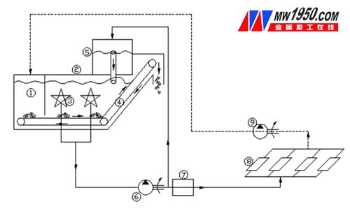
Figure 5 Schematic diagram of centralized cooling filtration system
(3) Advantages and Disadvantages of Centralized Cooling Filtration System Centralized cooling filtration has many characteristics, such as large circulation, large flow, large stroke, and fast heat dissipation. Compared with single-machine filtration cooling system, the life of cutting fluid is increased by about three times; PLC control can be adopted. High degree of automation, long service life, simple maintenance, easy to handle the chips (clamping, drying, etc.), good sealing, no odor in the summer air, good for environmental cleaning; cutting fluid is easy to control and maintain, only need The sampling control is carried out at the outlet of the clean liquid; the constant temperature control can be realized through the heat exchange system, and the cooling water inside and outside the plant can be cooled to bring the heat to the outside of the plant, which reduces the temperature in the summer plant and increases the comfort; the filtering precision is high. High filtration accuracy can extend tool life and reduce workpiece surface roughness. The oil skimmer can be installed to eliminate the oil in the cutting fluid and improve the service life of the cutting fluid; it is convenient for centralized treatment of the wastewater, and the wastewater can be directly discharged to the sewage treatment station for cleaning through the pipeline.
However, there are also many shortcomings, such as complicated wiring, long construction period, difficult construction, and large one-time investment. Once a failure occurs, the whole line may be shut down and the risk is high. If air return is used, a liquid return pump is needed for lifting. Since the agitation of the pump easily causes the cutting fluid to foam, higher requirements are placed on the defoaming property of the cutting fluid.
The advantages and disadvantages of centralized cooling filtration and single-machine cooling filtration can be seen in Table 3.
Centralized cooling filter single machine cooling filter
Advantages 1. The coolant is of the same brand, concentration, filtration precision, etc. 2. Improve the working environment 3. It can concentrate on the treatment of chips and solid impurities. 4. Unified management, which is beneficial to prolong the life of the coolant and reduce the discharge of waste liquid. 2 brands of coolant 2, according to the different processing technology, each sequence can be equipped with different concentrations of coolant 3, the production line process layout is flexible, easy to transform in the later 4, good independence, avoid mutual interference
Disadvantages 1. The position of the machine tool is fixed, and the possibility of contamination of the cutting fluid is increased. 2. The independence is poor. It is easy to cause collective shutdown of the filter system and the production line machine. 3. It is easy to cause foam problem. The quality of the cutting fluid is high. 1. Defoaming Poor performance and heat dissipation 2, a large number of chip processing systems, and complex chip processing 3, inspection, maintenance complex 4, serious environmental pollution
3. Cooling filter selection principles and success stories
For processing centers that are dispersed in small factories, a single-machine cooling filtration system is suitable. For large powertrain parts factories, such as engine blocks, cylinder heads, frames, and gearbox housings, large-scale centralized cooling filtration systems can be used due to large output, large number of machine tools, and the same cutting fluid type. The centralized cooling filtration system can greatly improve the life of cutting fluid, reduce production costs, achieve clean production, and improve the working environment of employees. Therefore, the system is characterized by advanced nature and environmental protection.
The basic parameters of the filter mainly include the filtration accuracy, the size of the filter medium, the flow rate, the size of the box and the amount of chips. For example, a certain cylinder production line of our company has an annual production capacity of 300,000 units. The cutting precision of machine cutting fluid is high (outside cooling 100μm/internal cooling 30μm), and the flow demand is large (8000L/min), so a centralized cooling filtration system is adopted. The specific scheme is the above-ground tank, the air returning liquid, the outer cooling filter unit adopts the star filter unit, and the internal cooling of the machine tool spindle adopts separate centrifugal filtration to ensure the internal cooling filtration requirement; the tank volume is generally the demand flow per minute. About 10 times, the volume of the tank is finally determined to be 120 m3. After nearly one year of use, the system has fully utilized the advantages of centralized treatment, high efficiency, energy conservation, environmental protection, and low operating costs.
to sum up
As a very important consumable in the powertrain factory, cutting fluid is not only used in large quantities, but also easily pollutes the environment, so it is necessary to conduct in-depth research. In this paper, the purification and filtration treatment of cutting fluid is studied. The filtration mode, filter medium and filter system size selection are studied. It is concluded that the large-scale machining workshop is suitable for centralized cooling system. At the same time, combined with our long-term experience, we will promote the advanced cutting fluid treatment concept and provide excellent solutions for the cutting fluid processing of automobile enterprises, thus revitalizing China's equipment manufacturing industry.
Dozer Parts
Dozer Parts,Bulldozer Spare Parts,Caterpillar Dozer Parts,Aftermarket Dozer Parts
JINING SHANTE SONGZHENG CONSTRUCTION MACHINERY CO.LTD , https://www.sdkomatsugenuineparts.com
