Intelligent anti-theft alarm system design (1)
This paper describes the design of the regional home intelligence burglar alarm system. The intelligent anti-theft alarm system is mainly composed of four parts: wireless anti-theft alarm probe, home host, community host, and regional host. Learn one by one:
First, the wireless anti-theft alarm probe design
The wireless anti-theft alarm probe is installed on each window of the living room. It has small size and low power consumption. It can be directly attached to the window. When the thief is found to be invaded, it can independently sound and light alarm and send a wireless alarm signal to the home host. The hardware structure is shown in Figure 1.

1, low power design
The wireless burglar alarm probe is powered by a button battery and requires a low power processor. This solution uses Atreel's AT TI ny44 processor. AT TI ny is Atmel's low-power family of products, and the ATTINy44 features three independently selectable low-power sleep modes that make the ATTIny44 a battery-powered device. Have a good performance. The application software can adjust the system clock frequency as needed to achieve optimal power performance, such as slowing down the clock frequency of some of the microprocessor modules when the system is idle. With the AVR Power Stop Sys te m, the user can turn off the timer , ADC and other energy consumption modules when the microprocessor is stopped. The ATtiny44 consumes less than 100 nA in PowerDown mode. The wireless sensor is required to be as small as possible for installation, and the ATti-ny44 compact package also makes the entire wireless sensor much smaller. ATtiny44 usually works in power-down state, which is the minimum power consumption mode. When there is an alarm signal, the processor wakes up from the interruption to determine whether it is a thief intrusion. If not, it returns to the power-down mode. If it is a thief, the wireless transmitting module is activated to transmit a wireless alarm message.
2. Infrared pyroelectric sensor
In nature, any object above the absolute temperature (-273 K) will produce an infrared spectrum. The infrared wavelengths emitted by objects of different temperatures are different. The infrared wavelength is related to temperature, and the amount of radiant energy is related to the surface temperature of the object. . The human body has a constant body temperature, generally around 37C, and emits infrared light of a specific wavelength of about 10 mm. The passive infrared probe works by detecting infrared rays emitted by the human body. The sensor of the passive infrared probe contains two pyroelectric elements connected in series, and the two polarization directions are opposite. The environmental background radiation has almost the same effect on the two pyroelectric elements, so that the discharge effect is mutually canceled. The detector has no signal output. The infrared rays are reinforced by the Fresnel filter and then collected into the pyroelectric element. When the infrared radiation is received, the component loses the charge balance and releases the charge outward. After the detection, the alarm signal can be generated.
3, wireless transmitter module
The wireless transmitter's wireless transmitter module uses Chipcon's CCII50 single-issue chip. The ClI50 has a wealth of frequency resources and requires very few external components. The CCII50 has a sleep state. When there is no alarm message, it can be set to the sleep state to reduce the battery power consumption. When there is an alarm message, the wireless transmitting module is woken up, and the wireless transmitting module is turned off after the transmitting of the alarm signal is completed.
Second, the home host design
The home host is the core of the whole family intelligent anti-theft alarm system. It can not only alarm after receiving the alarm signal, drive away the thieves, but also send alarm messages to the cell host and regional host to inform the security personnel to come as soon as possible. The home host hardware structure is shown in Figure 2.

1, wireless transceiver module
The home host adopts Chipcon's CCIIOO wireless transceiver chip, which can be used with CCII50 single-chip chip. It has rich frequency resources and high receiving sensitivity, which can fully meet the receiving task of indoor wireless sensor signals. After receiving the wireless alarm signal, CCII0O transmits the received data to the single-chip microcomputer , and the single-chip computer analyzes the data, and then issues an audible and visual alarm and a short message alarm information.
2, wireless sensor network
Wireless sensor network is a new information acquisition platform that can monitor and collect information of various monitoring objects in the network distribution area in real time, and send this information to the gateway node to achieve target detection and tracking within the specified range. It is fast and invulnerable. The regional home intelligent anti-theft alarm system uses the wireless sensor network principle to set up a wireless intelligent anti-theft alarm network. The wireless anti-theft alarm probe is a cluster node, the home host is a cluster head node, and the cell host is a gateway node. The alarm information of the wireless anti-theft alarm probe can be aggregated to the host of the cell in time, and the host of the cell is reflected in time, so that the security personnel can respond quickly. The structure of the wireless sensor network is shown in Figure 3.

3, the microprocessor
The home host has a slightly higher requirement for the microprocessor. The microprocessor is connected to the wireless transceiver module and the GSM module at the same time, and has a host computer communication interface. This program uses ATmegal28 microprocessor, ATmegal28 has 2 serial ports, and S PI interface, which can meet the above functional requirements. In addition, it also has a rich 1/0 port resource, which can be used to drive the sound and light alarm and relay action. ATmegal28 has a built-in 4 KB EEP ROM that can be erased 100,000 times. Because the home host needs to manage the location information and ID of the wireless anti-theft alarm probe, store the alarm call of the alarm user, the content of the alarm message, the number of alarms, etc., so the 4 KB EEP ROM can solve this problem well. After the microprocessor receives the alarm information from the wireless transceiver module, it needs to analyze the data, find the activated wireless sensor list, find the sensor corresponding to the ID number, read out the information, and insert the position information into the After the preset alarm message, it is sent to the alarm user through the GSM module according to the alarm user list.
4, GSM module
The GSM network has high communication quality, good confidentiality, large network capacity and strong anti-interference ability. It can realize global automatic roaming and provide users with various services such as voice, data and short messages. It is the most mature and perfect in China. The most widely used and widely used mobile communication system. The short message of the GSM network is information transmitted through the signaling channel, which is unique to the GSM communication network. It does not need to establish a connection by dialing, and can directly send the information to be sent to the short message service center SMSC, and then forward it to the final sink by the SMSC at an appropriate time. The short message service, like voice transmission and fax, is the main telecommunication service provided by the GSM digital cellular mobile communication network. It transmits through the wireless control channel, and completes the storage and forwarding functions through the short message service center. Each short message can send 70 Chinese characters, which can include the name of the alarm user, the specific address of the alarm location, and the location of the wireless burglar alarm probe. Clearly describe the location of the incident and ensure that security personnel can arrive at the scene in the first place.
5, keyboard and display
The keyboard can be used to set various functions of the home alarm, and the status of the home alarm host can be seen through the display. The basic configuration operations can be set via the keyboard, and some advanced settings need to be installed on the computer. The configuration software on the settings. The basic configuration allows the alarm system to work properly, and some users who are inconvenient to use the computer can easily use the alarm system. Basic configuration operations include home burglar alarm switches, alarm user settings, enable activation and group management, wireless burglar alarm probe registration and enable activation, and simple alarm log management.
6, configuration software
The home console is equipped with configuration software and is installed on a home computer. The main functions of the configuration software are:
1 alarm user settings. You can set the name, mobile number and activation status of the alarm user, which can be grouped and managed to distinguish the priority of different alarm users.
2 wireless anti-theft alarm probe settings. You can set the ID number of the wireless alarm, the window position and the enabled status of the wireless burglar alarm probe.
3 alarm SMS settings. Set the preset content of the alarm SMS. When there is a wireless anti-theft alarm probe to send the alarm information, you only need to insert the location information of the household name and the wireless anti-theft alarm probe into the preset alarm SMS, which can be directly sent to the GSM module for transmission.
4 alarm log management. You can view the details of the most recent alarm information and manage the alarm log information.
Third, the community host design
The host of the cell mainly manages the users in the residential area, and the security coverage covers the entire community. It is suitable for the installation of the community security department and performs security protection supervision for the entire community. The hardware structure of the cell host is shown in Figure 4.
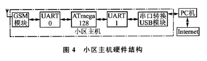
1, GSM module
Like the home alarm host, the cell host is equipped with the same GSM communication module. When the GSM module receives the alarm signal, it immediately transmits the alarm information to the microprocessor. The microprocessor transmits the SMS message to the _PC software through the serial port.
2, alarm function
The main function of the software is to display the alarm information transmitted by the microprocessor, display it in time, and issue an audible and visual alarm to remind the on-duty personnel to respond quickly and arrive at the scene as soon as possible.
3, data management
There are many users on the cell host, and you need to use the database for management. The host computer uses the sQL server for user data management. The upper computer software performs user management in the cell. When the user of the cell uses the alarm system for the first time, the user needs to send a registration short message to the cell host, or register the personal information by manually inputting to the cell host, and establish a database of the cell alarm user. . The upper computer software manages the alarm log, and each alarm is recorded in detail, which is convenient for searching afterwards.
Fourth, regional host design
The management scope of the regional host involves the entire region, and may include several communities within the region. The users are larger and suitable for the local public security department to install, which can effectively assist in the management of regional security. The hardware structure of the regional host is the same as that of the cell host, but the PC software is more powerful, with stronger database management functions and map positioning system. Due to the gradual expansion of regional host management, alarm methods may occur in parallel, so the most intuitive way to present is to display the exact location of the map directly when an alarm occurs. Therefore, the regional host has good map data information, and can query the geographic information data according to the address content of the alarm information, and directly display the geographical location corresponding to the alarm information on the map. If it can cooperate with the police GPS positioning system, the police can reach the scene faster and minimize user losses.
Summary of intelligent security alarm system design scheme (2)
First, the overall composition of the intelligent alarm system
The development and design of intelligent residential anti-theft and fire-fighting intelligent alarm system is based on the development of relevant technologies at home and abroad. According to the actual situation of China's housing construction and the coordinated development of various related aspects, it is truly intelligent to meet the living requirements of residents in the new era. The requirements of the alarm are determined.
This anti-theft fire alarm
The system is a new type of electronic security alarm system. The system is designed to combine electronic detection, intelligent control and telephone communication technology to form an anti-theft and fire alarm system. The overall structure of the system includes three modules: anti-theft fire detector, user-side automatic alarm and communication line. The block diagram of the system is shown in Figure 2.1.

The user-side automatic alarm is installed in the residential building to monitor and control different types of detectors in different parts of the residential building, and to process the data collected from each detector. When an abnormal situation occurs, the alarm is automatically dialed through the telephone line in the home and the central controller is established. The system does not need to occupy another telephone line. When there is an alarm signal, the alarm telephone has the priority of the telephone line.
The basic working process of the system:
At the user's precautionary site, once an emergency such as an intrusion or a fire occurs, the corresponding alarm detector (various fire prevention, anti-theft, and manual alarm buttons, etc.) immediately sends an alarm signal to the user-side automatic alarm. After receiving the alarm event, the automatic alarm will immediately confirm (multiple inspection interrupt signal). If no alarm is released after 50s and the alarm is confirmed, the live sound (buzzer) and light of the event will be performed. LED) alarm, at the same time, the user-side automatic alarm automatically dials the preset alarm phone number to the relevant department to perform voice alarm 2 . On the panel of the automatic alarm on the user side, there are LCD display, keyboard and three-color warning light (LED). The three-color warning lights respectively indicate the fire alarm or infrared/microwave double-proof fire alarm, normal operation and system failure status. , namely alarm light (red), work light (green) and fault light (yellow). The LCD displays the time when it is normal, and the time is displayed when the event occurs. The user alarm also has a probe fault alarm function to avoid false report due to power failure of the probe, and the fault light is lit when a fault occurs; if the probe is judged to be disconnected (cut), the sound and light alarm. If there is a false trigger and the alarm can be cancelled by the trigger delay time (505 timer), the user-side automatic alarm also has status information (if there is no AC power, the backup battery is insufficient). The function of reporting can realize the alarm for the preset ordinary telephone and mobile phone.
Second, the hardware system design
The automatic alarm software part adopts modular design and is divided into main control module, pick-up machine module, dialing module, voice module, display module and read/write data module. Using assembly language programming, in the KeiluVISion2 environment, the program is written to the microcontroller using the Top 2000-B programmer. The programming language software design uses MCS-51 assembly language to write related programs in the automatic alarm (such as dialing, voice, reading and writing X25045, etc.).
1, anti-theft detector circuit design
The microwave detector is a space detector for detecting any moving object in the prevention space. The microwave detector has high reliability, no requirements for light and heat source, and low detection environment requirements. In the microwave section, when transmitting at a frequency, within the range covered by the microwave energy, if an object moves, it will be reflected at another frequency, so that the transmission frequency and the reflection frequency have a frequency difference. This frequency difference is related to many factors, including the speed of the moving object, the radial angle of the detector, and so on.
In the actual circuit, the microwave circuit is generated by the oscillator circuit and emits near-microwave electromagnetic waves. The antenna converts the electrical signal into corresponding electromagnetic radiation to the surrounding space, and the radiation radius can reach more than 10m (if you want to continue to increase the radiation radius or improve) Sensitivity can be done by adjusting the size and orientation of the antenna). When someone is moving in the field, the reflected microwave will change in frequency, so that the microwave detector outputs a low-frequency electrical signal related to the speed of the human body. According to this characteristic, a microwave detector is also selected for detection of piracy.
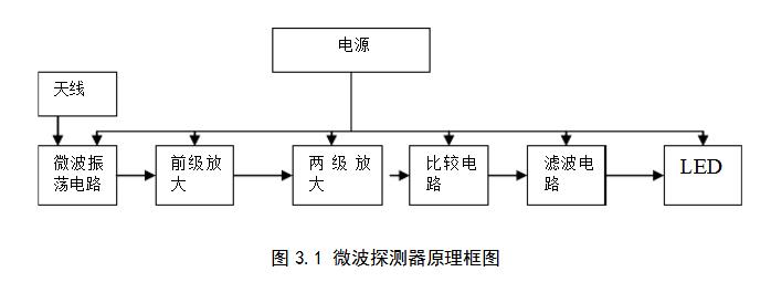
The loop antenna and its surrounding resistors, capacitors and MOS FETs form a near-microwave high-frequency self-oscillation circuit (its oscillation frequency is around 1 GHz). The principle of the microwave detector is shown in Figure 3.1. Later, the single-frequency and equal-amplitude signals generated by the oscillation are transmitted to the space through the external antenna to generate a three-dimensional microwave protection zone, and the antenna transmits both the oscillating signal and the echo. The reflected microwave signal is mixed with the original signal to generate a weak frequency shift signal, and the signal is sent to the amplifier for amplification. The amplified signal is sent to the window type amplitude comparison input terminal, and the detection signal of a certain intensity is converted by comparison. Outputs for equal amplitude pulses of different widths.
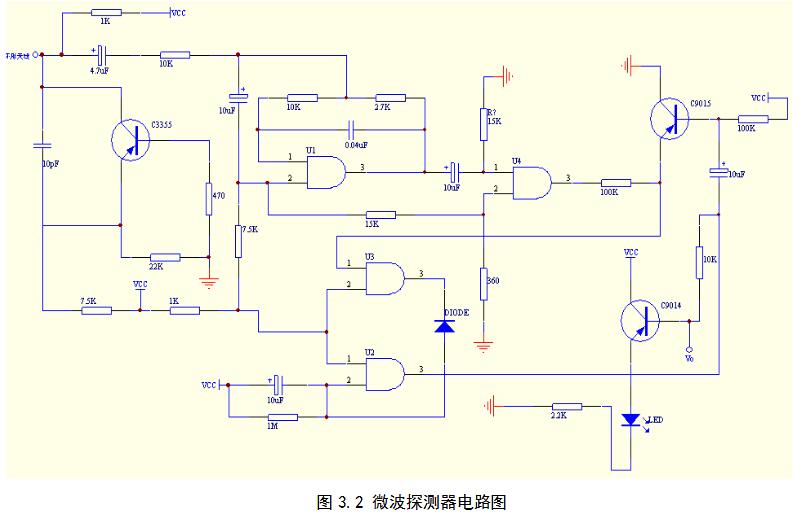
The main components used in the microwave detector circuit are single-supply general-purpose four operational amplifier KIA324P, loop antenna, microwave oscillation tube C3355 and some peripheral components, and external +6V power supply. Its circuit diagram is shown in Figure 3.2. When someone moves within the microwave protection zone, the oscillation frequency and amplitude change accordingly. According to the Doppler effect, the frequency of the fluctuation is related to the speed of the motion of the object, and the amplitude is related to the distance. After mixing, the high-frequency signal loses its effect because it is too high. The weak low-frequency signal is amplified by U1 for pre-amplification, and the 10 pF capacitor and 7.5K resistor constitute the charging circuit. The charging voltage is used as the reference voltage of the first-stage comparator U4. At the same time, the delay function is realized, that is, only when the preamplifier voltage is higher than the reference voltage, the output is high. At this time, C9015 is turned on, and finally the signal is compared by the window comparator composed of U2 and U3, and the detected output is detected. Signal [2. During the experiment, the alarm range is about 7-8 meters. When a valid signal is detected, there is a 20-second alarm signal output, and the LED illumination makes an early warning indication, which can effectively detect in real time. The circuit can operate over a wide voltage range (the standard voltage is 32V, but can actually operate over a wide voltage range) and is leveled when an abnormal signal is detected.
2, fire detector circuit design
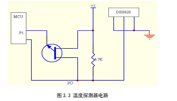
The temperature detector is powered by a digital temperature sensor DS18B20, 5V DC. The DS18BZ0's temperature measurement principle uses the relationship between the frequency of the temperature-sensitive oscillator and the temperature change, and directly converts the temperature signal into a serial digital signal. The temperature measurement can be realized by counting the temperature-dependent oscillator period by an internal counter. The DS18B20 in the detector uses a parasitic power supply to ensure sufficient current during the effective DS18B20 clock cycle. In Figure 3.3, a MOSFET and MCU I/O port are used to complete the bus pull-up on the DS18B20, and then pass another An I/O controls the DS18B20 and takes a temperature value.
3, the overall design of the user-side automatic alarm
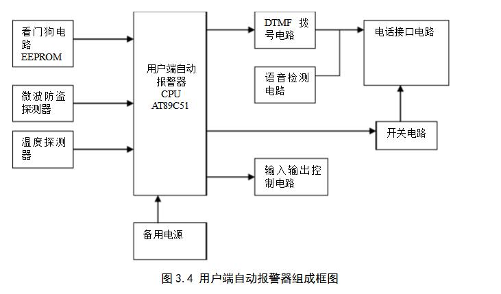
The user-side automatic alarm is the design focus of this topic. The block diagram of the automatic alarm is shown in Figure 3.4, which mainly includes the dialing module, voice module, telephone interface module, keyboard/password display module and power module . The alarm function is already in the Section 1.2 is described in detail and will not be described in detail here. This section focuses on the hardware circuit design related to the automatic dialing function.
The system microprocessor adopts AT89C51 single chip computer produced by American ATMEL Company. The AT89C51 uses the COMS process and is a low-power, high-performance 8-bit microcontroller that is fully compatible with the INTEL 8051 family of microcontrollers.
The AT89C51 has 4K bytes of Flash (flash) memory inside, which can be repeatedly erased and written. It can be modified repeatedly during the design of the program, compiled, and programmed to the microcontroller, suitable for the development and development of the minimum system of the microcontroller.
1) Automatic alarm circuit design
The automatic alarm circuit is shown in Figure 3.5. The clock circuit consists of two 30P capacitors and a 12MHz crystal. The reset circuit consists of a resistor, a capacitor, a diode, and a push button switch. It has a power-on reset and a manual reset. The INTO and INTl of the MCU are connected to the burglary and fire alarm sensors respectively to realize the collection of various alarms. In order to prevent the influence of the environmental interference signal on the trigger interrupt, when the response signal is interrupted, the interrupt signal is checked multiple times (such as 5 times), and the interrupt processing subroutine is executed when the interrupt signal is confirmed. Otherwise, it is considered that the external interference signal is not Perform alarm processing to effectively reduce the chance of false positives.
The system microprocessor adopts AT89C51 single chip computer produced by American ATMEL Company. The AT89C51 uses the COMS process and is a low-power, high-performance 8-bit microcontroller that is fully compatible with the INTEL 8051 family of microcontrollers. The AT89C51 has a 4K byte Flash (flash) memory inside, which can be repeatedly erased and written. It can be modified repeatedly during the design of the program, compiled, and programmed to the microcontroller, suitable for the development and development of the minimum system of the microcontroller.
2) Automatic alarm circuit design
The automatic alarm circuit is shown in Figure 3.5. The clock circuit consists of two 30P capacitors and a 12MHz crystal. The reset circuit consists of a resistor, a capacitor, a diode, and a push button switch. It has a power-on reset and a manual reset. The INTO and INT1 of the single-chip microcomputer are respectively connected with the burglar alarm and the fire alarm sensor to realize the collection of various alarms. In order to prevent the influence of the environmental interference signal on the trigger interrupt, when the response signal is interrupted, the interrupt signal is checked several times (such as 5 times), and the interrupt processing subroutine is executed when the interrupt signal is confirmed. Otherwise, it is considered that the external interference signal is not Perform alarm processing to effectively reduce the chance of false positives.
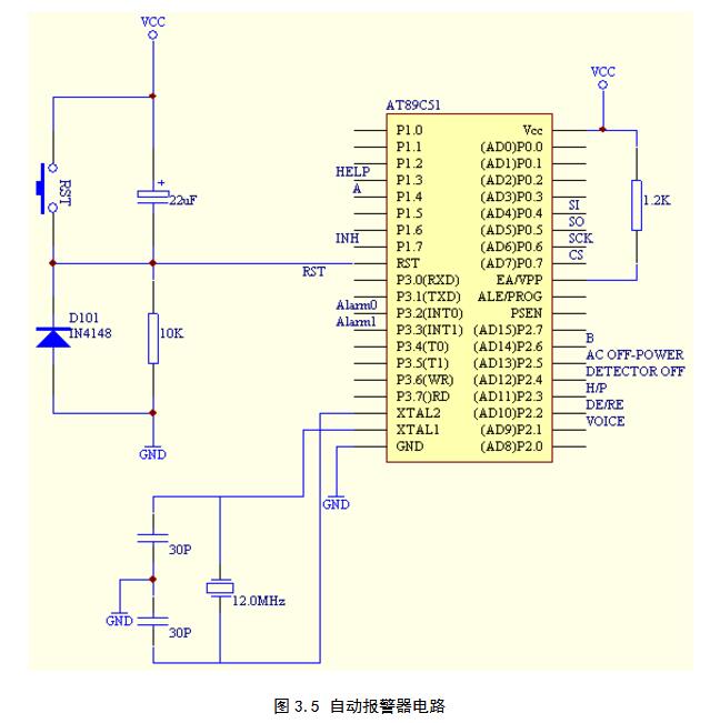
P2.1 is connected to the voice circuit to realize the playback control of the voice. P2.2 is connected to the data transmission and receiving chip selection terminal /RE (DE) of the communication interface conversion chip. P2.3 is connected to the telephone interface circuit to realize the control of the analog pick-up machine. P2.4 is connected to the probe drop detection terminal, and the MCU periodically polls the port. When it is normal, it is high level. When the low level is detected, the line alarm 0 is issued. P2.5 is connected to the AC power failure alarm signal (continued power supply after DC power failure, DC power supply, DC
After the power supply discharge is lower than the warning value, a DC power failure warning signal is sent to the automatic alarm. P1.0, P1.1, P1.2 are the three I/O lines connected to the keyboard circuit, and P1.3 is connected to the emergency call button. P1.5 is connected to the serial clock input terminal of the liquid crystal display, and P1.6 is connected to the data input end of the liquid crystal display. P1.7 is connected to the chip select terminal INH of the multi-way switch CD4051, and PI.4P2.6 is connected to the input terminals A and B of the multi-way switch respectively. The output of the multi-way switch is respectively connected to the alarm LED and the buzzer. When the alarm occurs, the output I/0 of the switch gives a high level signal. PO.0, P0.1, P0.2, and PO.3 are respectively connected to DO, D1, D2, and D3 of MT8888, and are used as a data bus. P2.0 is connected to the RS8 of the MT8888 to control the selection of the internal registers of the MT8888. P2.7 is connected to the cS of MT8888 to control the gating of MT8888.
P3.6 and P3.7 are connected to the WR and RD of MT8888 respectively to control the reading and writing of MT8888. P0.4 and P0.5 are connected to the serial input and serial output of EPROM. P0.6 and P0.7 are respectively connected to the serial clock input and chip select input of EPROM.
4, automatic dialing and voice alarm circuit design
1) Dial circuit
The automatic dialing circuit designed by the system can realize automatic paging through the telephone network, issue a distress signal to the designated institution or personnel, and briefly describe the nature and location of the accident, so that the rescuers can take corresponding measures to stop the accident. The main functions of the system are as follows:
1. Alarm priority function: host and user phone
The machine shares a telephone line. When it is not alarmed, it does not affect the normal use of the phone. The normal use of the phone does not affect or interfere with the host alarm. When the host alarms, the alarm call is given priority.
2. Automatic dialing function: You can set 1-6 groups of phone numbers or mobile phone numbers, each group does not exceed 15 digits.
3. The user can set and change the password for the automatic dialing alarm system.
4. Recording voice by yourself: voice broadcast, recorded by the user, recording “status†(such as someone breaking in, fire, etc.), user's name, address, phone number, etc. Automatically detect the call status: automatically detect the use status of the other party's telephone when the alarm occurs. If the other party is busy or no one is connected after the alarm, the reservation is skipped, and the next round is continued.
5. Memory storage function: This system uses X25045 as the memory component, all the inputs such as phone number and alarm information are not changed due to power loss.
5, keyboard and password display circuit design
The keyboard and password display circuit is responsible for the connection between the system and the outside world, and the display of data or commands, including: password input, password change input, telephone number setting, emergency call, recording, playback and other functions.
6, the design of the system power supply
1) Main power supply
The main power supply of this system is powered by DC power supply 5V and 6V. The schematic diagram is shown in Figure 3.13. The power section circuit is a typical 7805 / 7806 application circuit with two power outputs. The circuit has a short-circuit protection function, the transformer outputs 7V AC, is rectified by the bridge, the capacitor filter is sent to the 7805 / 7806 input, and finally the output sV / 6V DC. The resistor and red LED form the power operation indicating circuit, and the green LED and buzzer are used for the short circuit alarm indication.

2) Backup power supply
The fire detector should be monitored 24 hours a day, and no power failure is allowed. This requires the use of a backup power source. The use of the backup power supply as the main power supply to supplement the power supply of the single-chip system can make the single-chip microcomputer system not interrupt the power due to the sudden power failure of the power grid during the working period, and the main reason is that it can avoid the power interruption. Causing the entire computer system to ask questions. The main function of the backup power supply is to supply the battery power to the load when the input circuit is powered off. When the power supply returns to normal, the input circuit is responsible for supplying power to the load and charging the battery. Figure 3.14 shows the working principle of the online standby power supply. It is a DC online standby power supply that can generate the AC/DC power failure warning signal in a timely, correct and reliable manner.
The ICL8212 is a high performance programmable voltage detector that operates normally with a low supply voltage (1.8V) and a wide range (1.8-30v). Its performance is minimally affected by ambient temperature throughout the supply voltage. The range is also unaffected by changes in the supply voltage. When the detected voltage input to the THRE (preset threshold input) terminal is higher than 1.15V, the ICL8212 is a saturated transistor output, that is, the 3-pin OUT terminal outputs a low level; and when the 3-pin is lower than 1.15V, 4 The pin outputs a high level, and this high level is still valid until the power supply drops to 0V. The 2-pin HYST terminal is the hysteresis voltage setting terminal, and the hysteresis voltage setting prevents the detected voltage of the THRE terminal from being around 1.15V. , the OUT output is in an unstable state.
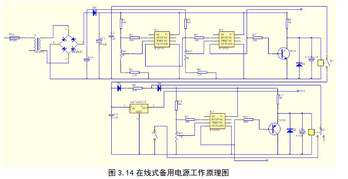
IC1 and IC2 two ICL8212 constitute a window voltage detector. When the AC voltage is in the normal working range during normal operation, the upper and lower detection thresholds are set reasonably. The window voltage detector IC2 consisting of IC1 and IC2 is 4 The output is high, the transistor Q1 is turned on, the K1 relay is connected, the regulated power supply works normally, the unregulated DC is D3:, the R9 is charged to the rechargeable battery, and the other is regulated by the system. Stable DC voltage. Once the AC power is lost, the output of the window voltage detector's output IC2 is low. It stores the power-down information in the automatic alarm EEPROM, the other control transistor Ql, and the AC loop and voltage regulation via the relay Kl. The device is disconnected, and the rechargeable battery continues to maintain power supply to the system for a certain period of time (the length of time is determined by the capacity of the selected rechargeable battery), realizing a DC online uninterruptible power supply network. Thereafter, when the rechargeable battery is powered for a certain period of time and the voltage drops to a certain value (not discharged to a very low level), the DC undervoltage/power-down detector composed of IC3 stops the rechargeable battery through the transistor Q2 and the relay K2. System power supply. S1 is a manual switch, and the automatic alarm is turned off when it is running, and is normally turned on.
PP Pressing Faucet,Pressing Type Faucet,Pp Pressing Type Faucet,Pressing Type Plastic Faucet
Cixi Ruisheng Electric Appliance Factory , https://www.rswatertap.com