The threaded connector has the advantages of simple assembly, convenient disassembly, and convenient maintenance, and is widely used in structural components of space optical remote sensors and assembly of the whole machine [1]. Since the space optical remote sensor experiences a severe vibration environment during the launch [2], the threaded connector is required to have a good anti-loosening ability. There are two types of anti-loose methods commonly used for threaded fasteners, namely, 1 by anti-loose parts (such as self-locking nuts, etc.) 2 by applying anti-loose rubber on the threads [3], and the threads can be firmly bonded after curing. Vice, to achieve the purpose of anti-loose. Because anti-loose rubber can reduce the number of mechanical parts and improve the reliability of threaded connection, it has become the main anti-loose means for threaded optical remote sensor thread connection. In the assembly of space optical remote sensors, the cement used for thread-locking connection mainly includes silicone rubber (such as GD414, D04 (L), etc.) and anaerobic adhesive (such as Loctite 243, J222, etc.), both at room temperature. The curing cycle is 15 days. Because the space optical remote sensor is very sensitive to the pre-tightening force of the screw near the mirror surface [4-9], with the increase of engineering application, it is found that the difference of the mirror surface shape of the screw before and after the glue coating is large in the process of using the anti-slack rubber; The plastic mirror surface is also different. The glue application only affects the pre-tightening force of the bolt, that is, the same pre-tightening force is applied under the same tightening torque, and the pre-tightening force of the screw is greatly different; the pre-tightening force of the different anti-slack rubber is also different. In the threaded connection pair close to the mirror surface, too large or too small pre-tightening force is harmful, that is, the pre-tightening force is too large, resulting in large deformation of the mirror surface and the connecting member will be vibrated in the vibration test, too small in the vibration environment. The connection is invalid due to loose connections [10-11]. It can be seen that the selection of the pre-tightening force and the accuracy control in the use of the threaded connector are the key to ensure the quality of the threaded connection. In view of the importance of the pre-tightening force in the threaded connection pair, this paper quantitatively studies the influence of the threaded anti-squeeze on the pre-tightening force of the threaded connection. In order to provide reference for the selection of anti-loose rubber and the selection of bolt fastening methods in the assembly of space optical remote sensors.
1 Basic principle of tightening torque and preload
1.1 Relationship between tightening torque and preload
The principle of the force of the threaded connector is shown in Figure 1.

A tightening torque of size T is applied to the bolt, and a preload force F is generated in the axial direction of the bolt. The relationship between the two is [12]

Where: D 1 is the friction radius of the nut support surface; t is the thread pitch; β is the thread elevation angle, the common thread β=30°; T 1 is the torque applied to overcome the friction between the nut and the connected support surface; T 2 is The torque is applied to overcome the friction between the pairs of threads; T 3 is the resistance torque generated by overcoming the force of the inclined surface of the thread, so that the connecting member generates a pre-tightening force. In general, T 1 is 50% of the tightening torque T, T 2 is 40%, and T 3 capable of generating the pre-tightening force is only 10% of the tightening torque T.
1.2 Main factors affecting the preload force
In engineering, for ease of application, the formula (1) is usually simplified to
T=KdF(5)
Where: K is the tightening torque coefficient [13-14]; d is the nominal diameter of the thread.

Bolt size and material The K value is only related to the friction coefficient μ v of the thread pair and the friction coefficient μ c of the nut and the connector or gasket contact surface. Whether the anaerobic or silicone rubber is applied to the threads affects the coefficient of friction μ v of the thread pair. If the glue overflows to the joint surface of the nut and the connected part, the friction coefficient μ c of the joint surface will be affected, and the tightening force coefficient K value will be affected, resulting in a certain tightening torque and a change in the pre-tightening force.
2 Introduction to the test plan
2.1 Description of the program
The test plan for detecting the influence of anti-loose rubber on the thread pre-tightening force is shown in Figure 2. The test piece is mainly composed of a box body, an M10×120mm bolt and an M10 nut. The box body is made of cast iron material, and the bolts and nuts are made of stainless steel.

2.2 Test principle
The calibrated torque wrench is used to control the screw tightening torque. The relationship between the preload force and the strain generated inside the nut is derived as follows: a certain tightening torque T is applied to the nut, and a pre-tightening force F is generated inside the bolt rod, and the bolt rod acts on the pre-tightening force. The lower part is elongated, and the tensile stress σ is generated inside the bolt. If the screw cross-sectional area is A, then there is
F=σA (7)
According to Hooke's law, the relationship between the internal tensile stress σ and the strain ξ in the elastic deformation range is
σ =ξE (8)
Where: E is the elastic modulus of the bolt material.
From equations (7) and (8)
F=ξEA (9)
Equation (9) shows that the pre-tightening force F generated inside the bolt within the range of elastic deformation is proportional to the screw strain ξ. Therefore, the strain gauge is attached to the bolt rod to monitor the strain of the bolt under different preloading forces and the pre-tightening force of the bolt.
2.3 strain measurement
The strain gauge can be obtained by attaching a strain gauge to the test piece, that is, the strain on the surface of the component is strained by the load, and the resistance strain piece attached to the surface of the component senses the strain and the resistance value changes, and the changed current is obtained by the resistance strain gauge or The voltage is recorded and the stress and strain on the surface of the component are obtained by a certain ratio conversion.

The alloy foil strain gauge used in this test is shown in Fig. 3. A resin paste is coated on one side of the foil, heated to be used as a substrate, and the other surface is photographicly etched (lithographically) to form a sensitive grid. The thickness of the alloy foil is 0.003 to 0.01 mm, and the thickness of the substrate is 0.03 to 0.05 mm. The strain gauge feels closer to the surface strain state of the test piece; the transverse effect coefficient is smaller, the heat dissipation condition is good, and the stronger signal is output through a larger current, thereby improving the measurement sensitivity; the foil grid size and shape are accurate, and can be made. Any shape, such as a strain gauge with a small gate length.
In order to monitor the amount of deformation of the bolt under different preloading forces, strain gauges are attached to the bolts. The bolt is partially flattened to ensure the quality of the bonding. A foil piece is attached to each of the flat grooves on both sides of the screw near the middle of the screw head, and the two strain gauges are backed up each other, as shown in Fig. 4.

2.4 Loading scheme
Take the bolt 1 in Fig. 5 as the research object, and measure the tightening torques of 10Nm, 15Nm, 20Nm, and 25Nm without applying the thread anti-squeezing rubber; apply D04 (L) thread anti-loose rubber on the thread to measure the tightening torque. They were 10Nm, 15Nm, 20Nm, and 25Nm, respectively, and were loaded 5 times in each working condition. Five sets of readings were obtained, the maximum and minimum values ​​were removed, and three sets of readings were taken for data analysis.
With bolt 2 as the object, the tightening torques measured under the condition of no thread anti-squeezing rubber are 10Nm, 15Nm, 20Nm, 25Nm respectively; the tightening torques measured after coating Loctite 243 thread anti-squeeze are 10Nm, 15Nm, 20Nm, 25Nm, respectively. The number of loadings per case is the same as that of bolt 1.

3 Experimental results and analysis
3.1 Test pieces and test equipment
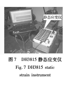
The modified bolt and the attached strain gauge are shown in Fig. 5, in which the bolts 1, 2 are test objects, and 3 is a spare part. The whole test component is shown in Figure 6. It consists mainly of the box body, the modified M10 bolt and the nut. The bolt strain was measured with a DH3815 static strain gauge. The test equipment is shown in Figure 7.

3.2 Test results
The test results of the strains of the bolts before and after applying D04(L) glue under different tightening torques are shown in Table 1. The test results of the strains of the bolts before and after the different tightening moments of the coatings are shown in Table 2. It can be seen from Table 2 that the test results in each state are reproducible.


3.3 Comparison and analysis of results
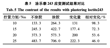
Comparing the average values ​​of the three sets of readings in Tables 1 and 2, the two bolts are subjected to the same tightening torque without glue. The strain test results generated inside the bolts are shown in Table 3. Silicone rubber (D04(L) The comparison of the internal strain test results of the front and rear bolts is shown in Table 4. The internal strain measurement results of the bolts before and after the coating of the 243 thread anti-slack rubber are shown in Table 5. It can be seen from the table 3 that the strain of the two bolts under the same tightening moment load has an error of nearly 30% without the glue, which indicates that the preload force of the bolt is controlled by the torque wrench method. After applying D04(L) anti-squeeze on the thread, the pre-tightening force is reduced by 50%~70% under the same tightening torque; the pre-tightening force is increased by 46%~98% under the same tightening torque after coating Loctite 243 anti-squeezing rubber, two kinds of glue The pre-tightening force changes the opposite direction. It means that if the torque is tightened by the torque wrench method, the relationship between the anti-squeeze and the thread pre-tightening force should be quantitatively tested before the formal assembly, otherwise the actual pre-tightening force will deviate greatly from the expected value.


4 Conclusion
Through the research on the influence of anti-loose rubber on the pre-tightening force of the threaded connection, the conclusions are as follows:
(1) In the assembly of structural parts of space optical remote sensor, the tightening torque of the screw is controlled by the torque wrench, and the error is close to 30%; the anti-loose rubber on the thread will have a great influence on the friction coefficient of the thread pair and the screw head and the joint surface. Different anti-slack adhesives have different effects on the friction coefficient.
(2) The tightening torque is the same. The pre-tightening force generated inside the bolt after the anti-loose rubber is applied will be seriously inconsistent with the design value, resulting in serious safety hazards. A quantitative study of the effect of gluing on the pre-tightening force of the threaded connection is required.
(3) The results of this paper have a strong guiding significance for the design of space optical remote sensor and the use of threaded anti-slack rubber in assembly. It is necessary to accurately control (accuracy needs to be higher than 30%) bolt pre-tightening connection area, and can not be tightened by torque wrench.
references
[1] Qiu Xuanhuai, Guo Keqian. Mechanical Design (Fourth Edition) [M]. Beijing: Higher Education Press, 1997.
[2] Xia Yilin, Wu Jiayu. Low-frequency vibration environment of space launch and its simulation [J]. Strength and Environment, 1998(1): 1-8.
[3] Guan Yang, Xu Wubin, Wang Guoan. Discussion on the anti-loose effect of thread locking glue [J]. Mechanical Research and Applications, 2013 (2): 170-172.
[4] Han Xu, Wu Qingwen, Dong Deyi, et al. Application of room temperature vulcanized rubber layer modeling in lens structure analysis [J]. Optics and Precision Engineering, 2010, 18(1): 118-125.
[5] Dong Deyi, Zhang Xuejun. Error evaluation of modal analysis of mirror components [J]. Optical Precision Engineering, 2011, 19(8): 1883-1894.
[6] Zhao Hongchao, Zhang Jingxu, Yang Fei, et al. Dynamic analysis of pre-tight eight-wing beam secondary mirror support structure [J]. Optical Precision Engineering, 2013, 21(5): 1199-1204.
[7] An Qichang, Zhang Jingxu, Zhang Limin. Dynamics of sub-mirror cable support structure of telescope[J].Infrared and Laser Engineering,2013,42(8):2115-2119.
[8] Wei Qingfang. The influence of screw preload on the assembly deformation of precision parts [J]. Mechanical Design and Manufacturing, 2013 (5): 216-218.
[9] Zhang Yongjuan, Zeng Guoying, Zhao Dengfeng, et al. HHT analysis of bolted joint structure under vibration environment [J]. Mechanical Design and Manufacturing, 2013 (11): 161-163.
[10] Zhao Dengfeng, Zeng Guoying. Research on the loosening process of bolt connection in vibration environment [J]. Vibration and Shock, 2010, 29 (10): 175-178.
[11] Wang Wei, Xu Hao, Ma Yue, et al. Research on self-relaxation mechanism of bolt connection under vibration conditions [J]. Vibration and Shock, 2014, 33(22): 198-202.
[12] Bu Yan. Thread connection design and calculation [M]. Beijing: Higher Education Press, 1995.
[13] Wang Peng, Chen Ansheng, Zhang Huiwu, et al. Experimental study on the influencing factors of bolt torque coefficient [J]. Experimental Mechanics, 2013, 28(3): 307-313.
[14] Jia Xianan, Li Wei, Yuan Yuan. Experimental study on the influencing factors of high-strength bolt torque coefficient [J]. Mechanical Engineer, 2004 (2): 42-44.
The LED emergency inverter is a combination of a white high-quality ABS shell and an external lithium ion battery , which is small in size and easier to hide in the ceiling . This emergency conversion kit is suitable for all external driver of LED lights in the wide voltage AC85-265V range , equipped with lithium ion battery that can be recharged up to 500 times , the emergency power supply has multiple protection functions , such as overcharge , over-discharge , short circuit protection , etc .

Led Inverter,Led Power Converter,Led Emergency Battery Driver,Emergency Light Conversion Kit
Jiangmen City Pengjiang District Qihui Lighting Electrical Appliances Co., Ltd , https://www.qihuilights.com